[Robot]---(Laser)---[Wall]
   |               ↑
   |<---Distance----|
RTX Lidar cannot perceive the “thing-in-itself (Ding an sich).” Instead, it provides processed data in a perceivable format (phenomenon). In other words, RTX Lidar does not see reality “as is,” but reconstructs the world into a form we can interpret within the frameworks we define (parameters, annotators, writers).
The RTX Lidar system consists of four core file types.
[1. Asset USD File] ←--→ [2. USDA Parameter File]
         ↓                        ↓
[3. Registered Config] ←--→ [4. JSON Template]
	       ↓                       ↓
    [LidarRtx Validation] ←--→ [Runtime Conversion]
		      ↓                     ↓
         [USD Property Integration]
		              ↓
         [RTX Engine Simulation]
End-to-End Data Flow Overview
→ LidarRtx integrates these and runs real-time simulation on the RTX engine.
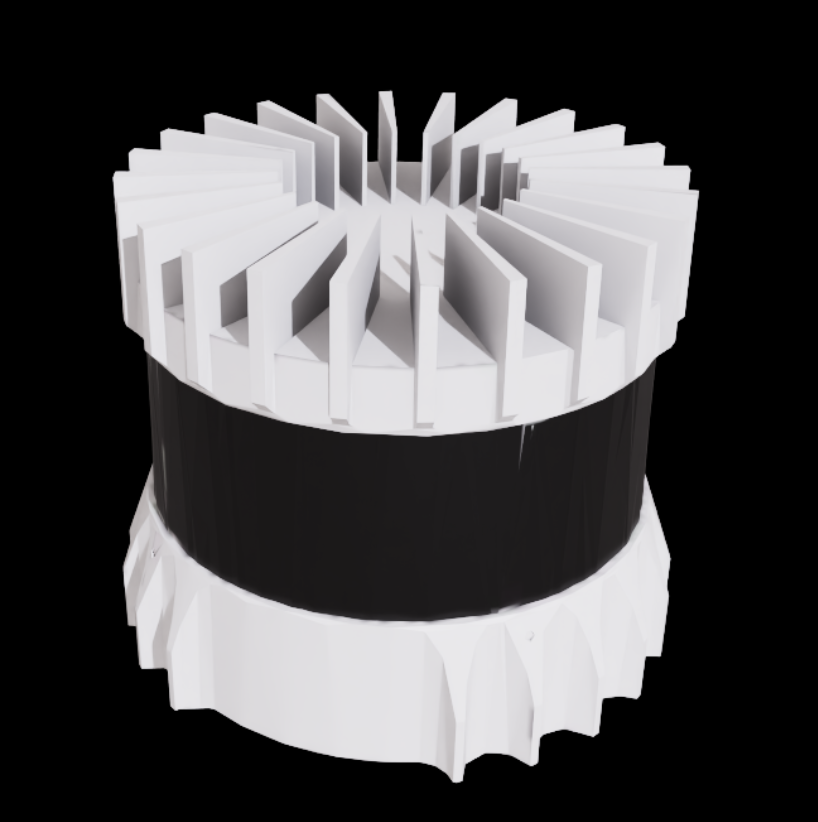
3.1 Asset USD File (3D Model + Variant Definitions)
Role: Integrates the lidar sensor’s visual representation and multiple configuration options in a single file.
Example Location: https://omniverse-content-staging.s3-us-west-2.amazonaws.com/Assets/Isaac/5.0/Isaac/Sensors/Ouster/OS0/OS0.usd
Structure:
OS0.usd
├── [3D Mesh] Visual model of the lidar sensor
├── [Material] Texture and material info
└── [Variant Set] Multiple configuration options
    ├── "OS0_REV6_128ch10hz512res"   # 512 resolution
    ├── "OS0_REV6_128ch10hz1024res"  # 1024 resolution
    ├── "OS0_REV6_128ch10hz2048res"  # 2048 resolution
    └── ... (more variants)
Key Characteristics:
3.2 USDA Parameter File (Precise Sensor Specs)
Role: Defines precise physical sensor parameters per variant in USD format.
Example Location:
#usda 1.0
(
    defaultPrim = "OS0_REV6_128_10hz_512_resolution"
    doc = "Generated from OS0_REV6_128ch10hz512res.json"
)

def OmniLidar "OS0_REV6_128_10hz_512_resolution" (
    prepend apiSchemas = ["OmniSensorGenericLidarCoreAPI"]
)
{
    # Basic sensor attributes
    float omni:sensor:Core:avgPowerW = 0.002
    float omni:sensor:Core:nearRangeM = 0.3
    float omni:sensor:Core:farRangeM = 50
    uint omni:sensor:Core:numberOfChannels = 128
    uint omni:sensor:Core:scanRateBaseHz = 10

    # Beam angles (128 channels)
    float[] omni:sensor:Core:emitterState:s001:azimuthDeg = [
        4.23, 1.41, -1.4, -4.21, 4.22, 1.42, -1.41, -4.22,
        4.23, 1.41, -1.42, -4.21, 4.23, 1.42, -1.4, -4.2,
        # ... total 128
    ]
    float[] omni:sensor:Core:emitterState:s001:elevationDeg = [
        44.5, 43.8, 43.1, 42.4, 41.7, 41, 40.3, 39.59,
        38.89, 38.19, 37.49, 36.79, 36.09, 35.39, 34.69,
        # ... total 128
    ]

    # Timing
    uint[] omni:sensor:Core:emitterState:s001:fireTimeNs = [
        762, 2287, 3812, 5337, 6862, 8387, 9912, 11437,
        # ... total 128
    ]

    # Channel mapping
    uint[] omni:sensor:Core:emitterState:s001:channelId = [
        1, 2, 3, 4, 5, 6, 7, 8, 9, 10, 11, 12, 13, 14, 15, 16,
        # ... total 128
    ]

    # Error model
    float omni:sensor:Core:azimuthErrorMean = 0
    float omni:sensor:Core:azimuthErrorStd = 0.01
    float omni:sensor:Core:elevationErrorMean = 0
    float omni:sensor:Core:elevationErrorStd = 0.01

    # Other properties...
    float omni:sensor:Core:rangeAccuracyM = 0.03
    float omni:sensor:Core:rangeResolutionM = 0.001
    token omni:sensor:Core:rayType = "IDEALIZED"
    uint omni:sensor:Core:reportRateBaseHz = 5120
    token omni:sensor:Core:rotationDirection = "CW"
    token omni:sensor:Core:scanType = "ROTARY"
    string omni:sensor:modelName = "OS0_REV6_128_10hz_512_resolution"
    float omni:sensor:tickRate = 10
}
Parameter Categories:
| Parameter Group | Examples | Description |
|---|---|---|
| Basic Sensor Attributes | avgPowerW, nearRangeM, farRangeM | Physical characteristics |
| Scan Settings | scanRateBaseHz, numberOfChannels | Scan speed, channel count |
| Beam Layout | azimuthDeg[], elevationDeg[] | Exact beam angles |
| Timing | fireTimeNs[] | Fire timing per beam |
| Channel Mapping | channelId[] | Beam ↔ channel mapping |
| Error Model | azimuthErrorStd, elevationErrorStd | Angular measurement errors |
Key Characteristics:
3.3 Registered Lidar Config File (Supported Model List)
Role: Defines all officially supported models and variants for RTX Lidar.
File Location: source/extensions/isaacsim.sensors.rtx/python/impl/supported_lidar_configs.py
Key Characteristics:
Examples of Officially Supported Lidar Models and Variants
By Manufacturer:
| Manufacturer | Model | # of Variants | Notes |
|---|---|---|---|
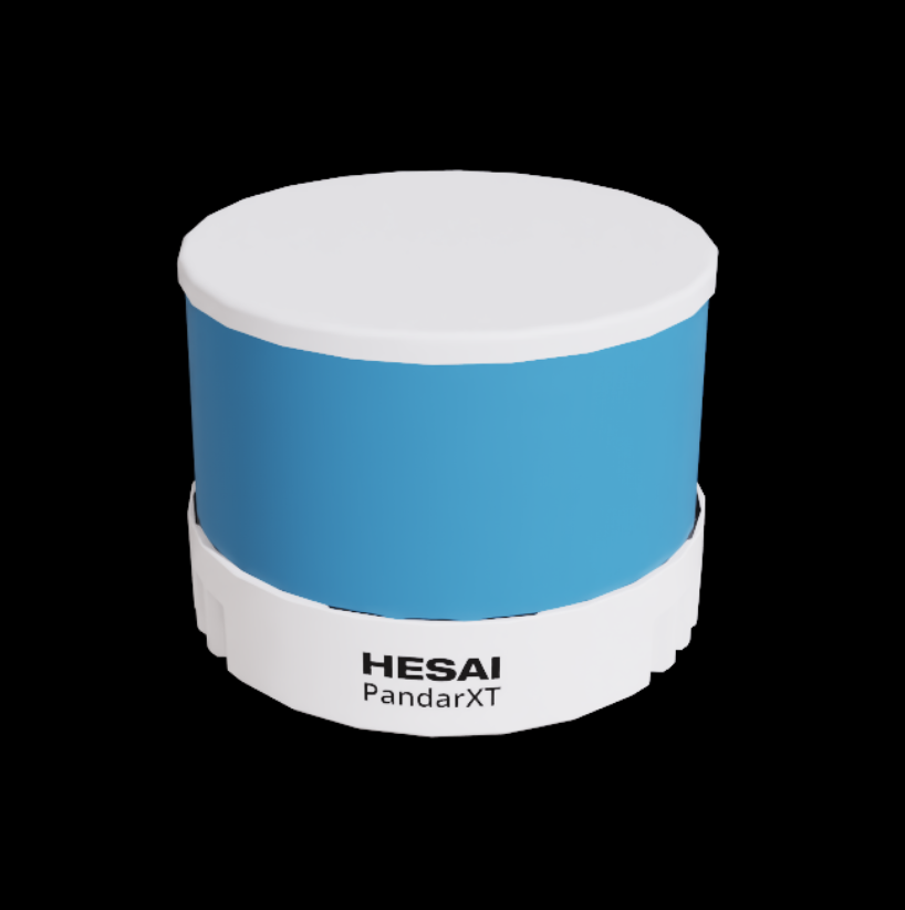
| HESAI | XT32_SD10 | - | High-resolution multibeam |
| NVIDIA | Debug_Rotary | - | Dev/debug use |
| NVIDIA | Example_Rotary | - | Rotary lidar example |
| NVIDIA | Example_Solid_State | - | Solid-state lidar example |
| Ouster | OS0 | 10 | Short-range high-res |
| Ouster | OS1 | 15 | Mid-range general-purpose |
| Ouster | OS2 | 10 | Long-range high-performance |
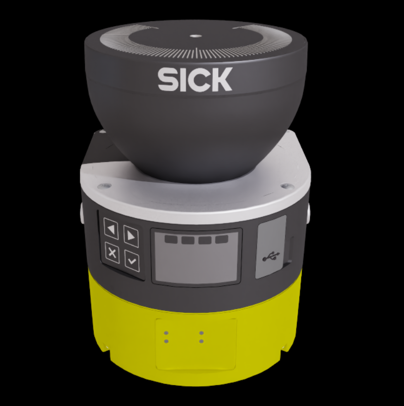
| SICK | microScan3 | 5 | Compact industrial |
| SICK | picoScan150 | 10 | Ultra-compact |
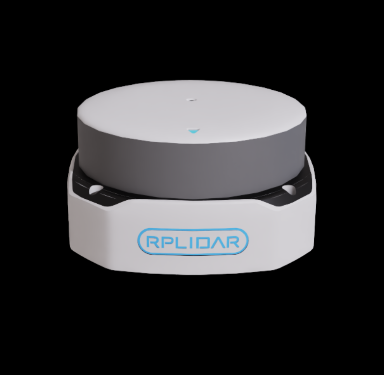
| Slamtec | RPLIDAR_S2E | - | Cost-effective SLAM |
| ZVISION | ML30S, MLXS | - | Automotive solid-state |
Manufacturer Highlights:
| Manufacturer | Characteristics | Variant Example |
|---|---|---|
| Ouster | High-res 3D lidar | OS0_REV6_128ch10hz1024res |
| SICK | Industrial lidar | Normal_1, Normal_2 |
| NVIDIA | Educational/prototyping | No variants (single setup) |
| SLAMTEC | 2D lidar | No variants |
Variant Naming Rules:
{model}_{revision}_{channels}ch{freq}hz{resolution}resNormal_{index} or Extended_{index}Full configs Code:
# SPDX-FileCopyrightText: Copyright (c) 2025 NVIDIA CORPORATION & AFFILIATES. All rights reserved.
# SPDX-License-Identifier: Apache-2.0

"""Configuration definitions for supported Lidar sensors in Isaac Sim.

This module defines the supported Lidar sensor configurations and their variants
that can be used with the RTX sensor system. It includes configurations for various
manufacturers.
"""

# Expected name of Lidar prim variant sets
SUPPORTED_LIDAR_VARIANT_SET_NAME = "sensor"

# Map supported Lidar asset paths to their variants
SUPPORTED_LIDAR_CONFIGS = {
    "/Isaac/Sensors/HESAI/XT32_SD10/HESAI_XT32_SD10.usd": set(),
    "/Isaac/Sensors/NVIDIA/Debug_Rotary.usda": set(),
    "/Isaac/Sensors/NVIDIA/Example_Rotary_2D.usda": set(),
    "/Isaac/Sensors/NVIDIA/Example_Rotary.usda": set(),
    "/Isaac/Sensors/NVIDIA/Example_Solid_State.usda": set(),
    "/Isaac/Sensors/NVIDIA/Simple_Example_Solid_State.usda": set(),
    "/Isaac/Sensors/Ouster/OS0/OS0.usd": {
        "OS0_REV6_128ch10hz1024res",
        "OS0_REV6_128ch10hz2048res",
        "OS0_REV6_128ch10hz512res",
        "OS0_REV6_128ch20hz1024res",
        "OS0_REV6_128ch20hz512res",
        "OS0_REV7_128ch10hz1024res",
        "OS0_REV7_128ch10hz2048res",
        "OS0_REV7_128ch10hz512res",
        "OS0_REV7_128ch20hz1024res",
        "OS0_REV7_128ch20hz512res",
    },
    "/Isaac/Sensors/Ouster/OS1/OS1.usd": {
        "OS1_REV6_128ch10hz1024res",
        "OS1_REV6_128ch10hz2048res",
        "OS1_REV6_128ch10hz512res",
        "OS1_REV6_128ch20hz1024res",
        "OS1_REV6_128ch20hz512res",
        "OS1_REV6_32ch10hz1024res",
        "OS1_REV6_32ch10hz2048res",
        "OS1_REV6_32ch10hz512res",
        "OS1_REV6_32ch20hz1024res",
        "OS1_REV6_32ch20hz512res",
        "OS1_REV7_128ch10hz1024res",
        "OS1_REV7_128ch10hz2048res",
        "OS1_REV7_128ch10hz512res",
        "OS1_REV7_128ch20hz1024res",
        "OS1_REV7_128ch20hz512res",
    },
    "/Isaac/Sensors/Ouster/OS2/OS2.usd": {
        "OS2_REV6_128ch10hz1024res",
        "OS2_REV6_128ch10hz2048res",
        "OS2_REV6_128ch10hz512res",
        "OS2_REV6_128ch20hz1024res",
        "OS2_REV6_128ch20hz512res",        "OS2_REV7_128ch10hz1024res",        "OS2_REV7_128ch10hz2048res",        "OS2_REV7_128ch10hz512res",        "OS2_REV7_128ch20hz1024res",        "OS2_REV7_128ch20hz512res",    },    "/Isaac/Sensors/Ouster/VLS_128/Ouster_VLS_128.usd": set(),    "/Isaac/Sensors/SICK/microScan3/SICK_microScan3.usd": {        "Normal_1",        "Normal_2",        "Normal_4",        "Normal_5",        "Normal_6",    },    "/Isaac/Sensors/SICK/multiScan136/SICK_multiScan136.usd": set(),    "/Isaac/Sensors/SICK/multiScan165/SICK_multiScan165.usd": set(),    "/Isaac/Sensors/SICK/nanoScan3/SICK_nanoScan3.usd": {        "CAAZ30AN1",    },    "/Isaac/Sensors/SICK/picoScan150/SICK_picoScan150.usd": {        "Normal_1",        "Normal_2",        "Normal_3",        "Normal_4",        "Normal_6",        "Normal_7",        "Normal_8",        "Normal_9",        "Normal_10",        "Normal_11",    },    "/Isaac/Sensors/SICK/TIM781/SICK_TIM781.usd": set(),    "/Isaac/Sensors/Slamtec/RPLIDAR_S2E/Slamtec_RPLIDAR_S2E.usd": set(),    "/Isaac/Sensors/ZVISION/ZVISION_ML30S.usda": set(),    "/Isaac/Sensors/ZVISION/ZVISION_MLXS.usda": set(),}
3.4 JSON Template (User-Friendly Configuration)
File Location: source/extensions/isaacsim.sensors.rtx/data/lidar_configs/NVIDIA/Simple_Example_Solid_State.json
Role: Provides a user-friendly format and compatibility with external tools.
Full JSON Template:
{
  "class": "sensor",
  "type": "lidar",
  "name": "Simple Solid State",
  "driveWorksId": "GENERIC",
  "profile":
  {
    "scanType": "solidState",
    "intensityProcessing": "normalization",
    "rotationDirection": "CW",
    "rayType": "IDEALIZED",
    "nearRangeM": 1.0,
    "farRangeM": 200.0,
    "effectiveApertureSize": 0.0145,
    "focusDistM": 0.16,
    "rangeResolutionM": 0.004,
    "rangeAccuracyM": 0.025,
    "avgPowerW": 0.002,
    "minReflectance": 0.1,
    "minReflectanceRange": 270.0,
    "wavelengthNm": 1550.0,
    "pulseTimeNs": 6,
    "maxReturns": 2,
    "scanRateBaseHz": 30.0,
    "reportRateBaseHz": 30,
    "numberOfEmitters": 12,
    "numberOfChannels": 12,
    "rangeCount": 1,
    "ranges": [
      {"min": 0.5, "max": 300}
    ],
    "azimuthErrorMean": 0.0,
    "azimuthErrorStd": 0.025,
    "elevationErrorMean": 0.0,
    "elevationErrorStd": 0.025,
    "stateResolutionStep": 1,
    "numLines": 3,
    "numRaysPerLine": [4, 4, 4],
    "emitterStateCount": 1,
    "emitterStates": [
      {
        "azimuthDeg": [
          -2, -1, 1, 2,
          -1.5, -0.5, 0.5, 1.5,
          -2.4, -1.4, 1.4, 2.4
        ], "_commentOnAzimuth": "Flat Scan is expecting equal angles between each emitter in the line it uses",
        "elevationDeg": [
          -8, -8, -8, -8,
           0, 0,  0,  0,
            8,  8,  8, 8
          ], "_commentOnElevation": "Flat Scan use the line with elevation nearest 0 as it's first line entry",
        "fireTimeNs": [
          0,3300000,6600000,9900000,
          13300000,16600000,19900000,23300000,
          26600000,29900000,31500000,33300000],
        "channelId": [
          0,1,2,3,
          4,5,6,7,
          8,9,10,11],
        "rangeId": [
          0, 0, 0, 0,
          0, 0, 0, 0,
          0, 0, 0, 0
        ],
        "bank": [
          11, 10, 9, 8,
           7,  6, 5, 4,
           3,  2, 1, 0
        ]      }    ],    "intensityMappingType": "LINEAR"  }}
Parameter Details
| Parameter | Meaning (EN) | Description (KR→EN) |
|---|---|---|
| class | Sensor class | Sensor category (always sensor) |
| type | Sensor type | Sensor type (lidar here) |
| name | Sensor name | Name of the sensor |
| driveWorksId | DriveWorks ID | Sensor ID for DriveWorks |
| scanType | Scan type | Scanning method (e.g., solidState) |
| intensityProcessing | Intensity processing | Processing mode for intensity data |
| rotationDirection | Rotation direction | CW/CCW |
| rayType | Ray type | Ray model (e.g., IDEALIZED) |
| nearRangeM | Near range (m) | Minimum measurable distance |
| farRangeM | Far range (m) | Maximum measurable distance |
| effectiveApertureSize | Effective aperture size (m) | Effective aperture |
| focusDistM | Focus distance (m) | Focus distance |
| rangeResolutionM | Range resolution (m) | Distance resolution |
| rangeAccuracyM |
By Parameter Group:
| Group | Key Params | Description |
|---|---|---|
| Basic Info | class, type, name, driveWorksId | Identification and external integration |
| Physical Properties | nearRangeM, farRangeM, avgPowerW, wavelengthNm | Hardware-level attributes |
| Scan Settings | scanType, scanRateBaseHz, numberOfEmitters, numberOfChannels | Scan mode, speed, channels |
| Accuracy/Resolution | rangeResolutionM, rangeAccuracyM, effectiveApertureSize | Measurement fidelity |
| Error Model | azimuthErrorStd, elevationErrorStd, azimuthErrorMean | Sensor error simulation |
| Beam Geometry | azimuthDeg[], elevationDeg[], numLines, numRaysPerLine[] | Spatial beam arrangement |
| Timing | fireTimeNs[], pulseTimeNs, reportRateBaseHz | Temporal settings |
| Data Processing | intensityProcessing, intensityMappingType, maxReturns | Output processing |
4.1 Relationship Diagram
[1. Asset USD] ←--→ [2. USDA Parameters]
	      ↓                     ↓
[3. Registered Config] ←--→ [4. JSON Template]
	      ↓                     ↓
    [LidarRtx Validation] ←--→ [Runtime Conversion]
		      ↓                     ↓
         [USD Property Integration]
			              ↓
         [RTX Engine Simulation]
4.2 Actual Data Flow
Scenario 1: Using a USD Asset
1. User: LidarRtx(config="/Isaac/Sensors/Ouster/OS0/OS0.usd", variant="OS0_REV6_128ch10hz512res")
2. Validation: Check support in supported_lidar_configs.py
3. Load: Pull the corresponding USDA parameters for the variant from the Asset USD
4. Apply: USD properties are applied directly to the RTX engine
5. Simulation: RTX ray tracing runs
Scenario 2: Using a JSON Template
1. User: LidarRtx(config="Simple_Example_Solid_State")
2. Lookup: Search JSON in data/lidar_configs/
3. Convert: JSON → USD properties (SensorNodeUtils.cpp)
4. Apply: Converted USD properties applied to the RTX engine
5. Simulation: RTX ray tracing runs
4.3 Priority and Selection Criteria
Processing Priority:
Recommended by Use Case:
| Purpose | Recommended Type | Why |
|---|---|---|
| Real hardware simulation | USD Asset + Variant | Manufacturer-accurate data |
| Rapid prototyping | JSON Template | Easy to edit |
| Education/learning | JSON Template | Readability |
| ROS/DriveWorks integration | JSON Template | External compatibility |
| High-precision research | USD Asset + Variant | Highest fidelity |
RTX Lidar is a system where four core components work together:
The LidarRtx class integrates these and provides real-time ray-tracing lidar simulation on the RTX engine. Depending on your goal, you can flexibly choose between high-fidelity hardware simulation (USD) and rapid prototyping (JSON).
5.1 Prim (OmniLidar Prim)
Code Example (Creating a Prim)
# Specify prim_path when creating LidarRtx
# Location: exts/isaacsim.sensors.rtx/isaacsim/sensors/rtx/impl/lidar_rtx.py
lidar = LidarRtx(prim_path="/World/lidar", ...)
# Location: exts/isaacsim.sensors.rtx/isaacsim/sensors/rtx/impl/lidar_rtx.py
if is_prim_path_valid(prim_path):
    ...
else:
    _, sensor = omni.kit.commands.execute(
        "IsaacSensorCreateRtxLidar",
        translation=Gf.Vec3d(...),
        orientation=Gf.Quatd(...),
        path=prim_path,
        ...)
5.2 LidarRtx Class
Code Example (Class Declaration and Key Methods)
# Location: exts/isaacsim.sensors.rtx/isaacsim/sensors/rtx/impl/lidar_rtx.py
class LidarRtx(BaseSensor):
    ...
    def __init__(self, prim_path: str, name: str = "lidar_rtx", ...):
        ...
    def initialize(self, ...):
        ...
    def attach_annotator(self, annotator_name: str):
        ...
    def attach_writer(self, writer_name: str):
        ...
    def get_current_frame(self) -> dict:
        ...
# Location: exts/isaacsim.sensors.rtx/docs/rtx_lidar.md (usage)
lidar = LidarRtx(prim_path="/World/lidar", position=[0,0,1], name="lidar")
lidar.initialize()
5.3 Annotator (Data Generator)
Code Example (Attaching Annotators)
# Location: exts/isaacsim.sensors.rtx/isaacsim/sensors/rtx/impl/lidar_rtx.py
lidar.attach_annotator("GenericModelOutputLidarPointAccumulator")  # 3D point cloud
lidar.attach_annotator("IsaacComputeRTXLidarFlatScan")  # 2D flat scan (for 2D lidars)
exts/isaacsim.sensors.rtx/isaacsim/sensors/rtx/impl/lidar_rtx.py (attach_annotator)5.4 Writer (Visualizer/Exporter)
Code Example (Attaching Writers)
# Location: exts/isaacsim.sensors.rtx/isaacsim/sensors/rtx/impl/lidar_rtx.py
lidar.attach_writer("RtxLidarDebugDrawPointCloud")  # visualize point cloud
exts/isaacsim.sensors.rtx/isaacsim/sensors/rtx/impl/lidar_rtx.py (attach_writer)5.5 End-to-End Data Flow Example
# Location: exts/isaacsim.sensors.rtx/docs/rtx_lidar.md (usage)
from isaacsim.sensors.rtx import LidarRtx
lidar = LidarRtx(prim_path="/World/lidar", position=[0,0,1], name="lidar")
lidar.initialize()
lidar.attach_annotator("GenericModelOutputLidarPointAccumulator")
lidar.attach_writer("RtxLidarDebugDrawPointCloud")

frame = lidar.get_current_frame()
print(frame["pointCloud"])  # 3D points generated by the annotator
exts/isaacsim.sensors.rtx/isaacsim/sensors/rtx/impl/lidar_rtx.py .Share this post:
| Range accuracy (m) |
| Distance accuracy |
| avgPowerW | Average power (W) | Average laser power |
| minReflectance | Minimum reflectance | Minimum reflectance threshold |
| minReflectanceRange | Minimum reflectance range (deg) | Angle range for threshold |
| wavelengthNm | Wavelength (nm) | Laser wavelength |
| pulseTimeNs | Pulse time (ns) | Pulse duration |
| maxReturns | Maximum returns | Max number of returns |
| scanRateBaseHz | Scan rate (Hz) | Base scan frequency |
| reportRateBaseHz | Report rate (Hz) | Output rate |
| numberOfEmitters | Number of emitters | Number of laser emitters |
| numberOfChannels | Number of channels | Channel count |
| rangeCount | Range count | Number of range bins |
| ranges | Ranges | Min/max for each range bin |
| azimuthErrorMean | Azimuth error mean | Mean azimuth error |
| azimuthErrorStd | Azimuth error std | Std dev of azimuth error |
| elevationErrorMean | Elevation error mean | Mean elevation error |
| elevationErrorStd | Elevation error std | Std dev of elevation error |
| stateResolutionStep | State resolution step | State step resolution |
| numLines | Number of lines | Number of scan lines |
| numRaysPerLine | Number of rays per line | Rays per line |
| emitterStateCount | Emitter state count | Number of emitter states |
| emitterStates | Emitter states | Per-state angle/timing arrays |
| azimuthDeg | Azimuth degrees | Azimuth angles per emitter |
| elevationDeg | Elevation degrees | Elevation angles per emitter |
| fireTimeNs | Fire time (ns) | Fire timing per emitter |
| channelId | Channel ID | Channel ID per emitter |
| rangeId | Range ID | Range bin ID per emitter |
| bank | Bank | Emitter group/bank |
| intensityMappingType | Intensity mapping type | Mapping method for intensity |
| _commentOnAzimuth | Comment on azimuth | Comment on azimuth array |
| _commentOnElevation | Comment on elevation | Comment on elevation array |